Francis Turbine Working Principle
Francis Turbine
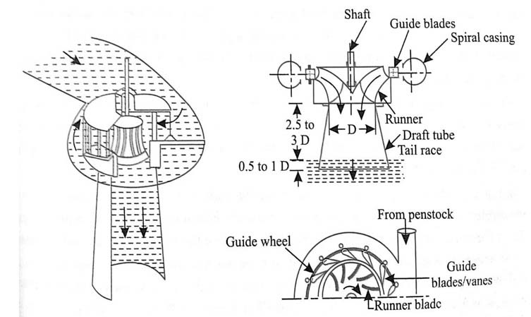
The main parts of a Francis Turbine are
- Penstock: That is a large size conduit that conveys water upstream of the dam/reservoir before the turbine runner.
- Spiral/scroll casing: This constitutes a closed passage whose cross-sectional space gradually decreases along each flow direction; some area is maximum at the inlet including nearly zero at any exit.
- Guide vanes/wicket gates: Certain vanes direct the water above the runner at an angle appropriate so the design. Each motion to them is given by means regarding a handwheel either automatically with a governor.
- Governing mechanism: This changes the position of one guide blade/vanes to affect a variation in water flow rate during the load conditions next to the turbine change.
- Runner and runner blades: Special driving force on the runner is both due to impulse further reaction effects. A unique number of runner blades usually ranges between 16 to 24.
- Draft tube: A gradually expanding tube discharges water, passing within the runner, into the tailrace.
Velocity Diagram also Work Done like Francis Turbine

Some work done per second at the runner with water is
=pav1[Vw1u1+-Vw2u2]
pQ[Vw1u1+-Vw2u2]
(As av1 = Q)
Where,
Vw1= Velocity of whirl at the inlet
Vw2 = Velocity of whirl at an outlet
u1 = Tangential velocity at inlet
= πD1N/60,
Where,
D1 = Outer diameter of the runner
u2 = Tangential velocity at the outlet
= πD2N/60,
Where,
D2 = Inner diameter of a runner,
N = Speed of turbine in RPM
The work is done per second per unit weight of water per second
(pQ[Vw1u1+-Vw2u2]) / pQg
=(1/g)[Vw1u1+-Vw2u2]
+ve sign acts taken if angle β exists as an acute angle.
If β is an obtuse angle then the –ve sign is taken.
If β = 90o, then and work done per second per unit weight of water per second is
=(1/g)[Vw1u1]


